Brake test system
VMS 3400 pedal wire control/pedal actuator testing system
Generally, in order to evaluate the vehicle's driving performance, traditional test methods have been used to measure the vehicle's acceleration performance. In addition to testing the acceleration performance of the vehicle, a lot of driving performance evaluation tests that use the accelerator pedal control quantitatively, precisely and repeatedly are required. For the test driver, it was very difficult to maintain the accelerator pedal opening quantitatively and accurately, or to control the accelerator opening change speed uniformly, or to repeatedly perform such an operation constantly.
Therefore, there is a need for a drive controller that can control the vehicle's accelerator pedal opening accurately and quantitatively with excellent repeatability. These drive controllers can perform accelerator pedal opening control repeatedly according to the specified mode, or in some cases, including brake pedal control.
The drive controller is essential for a chassis dynamo test that repeatedly drives a predetermined drive curve or a repeated driving test according to a specified mode on a proving ground. Instead of using an accelerator and brake pedal control by a test driver, an accurate, repeatable accelerator pedal controller is used now to perform driving performance evaluation tests with more accurate and repeatable reproducibility.

The VMS3400 generates exactly the same type of signal as the signal input from the APS/BPS and sends it to the ECU. The ECU recognizes this signal as an accelerator and brake pedal signal operated by the driver and controls the vehicle normally.
In addition to the general analog type, VMS3400 provides APS/BPS connection function of SENT type signal. which APS/BPS connection method is impossible, VMS3400 provides Pedal Robot which can control Accelerator and Brake pedal. VMS3400 can be used in combination with APS/BPS signal control method.
Key Features
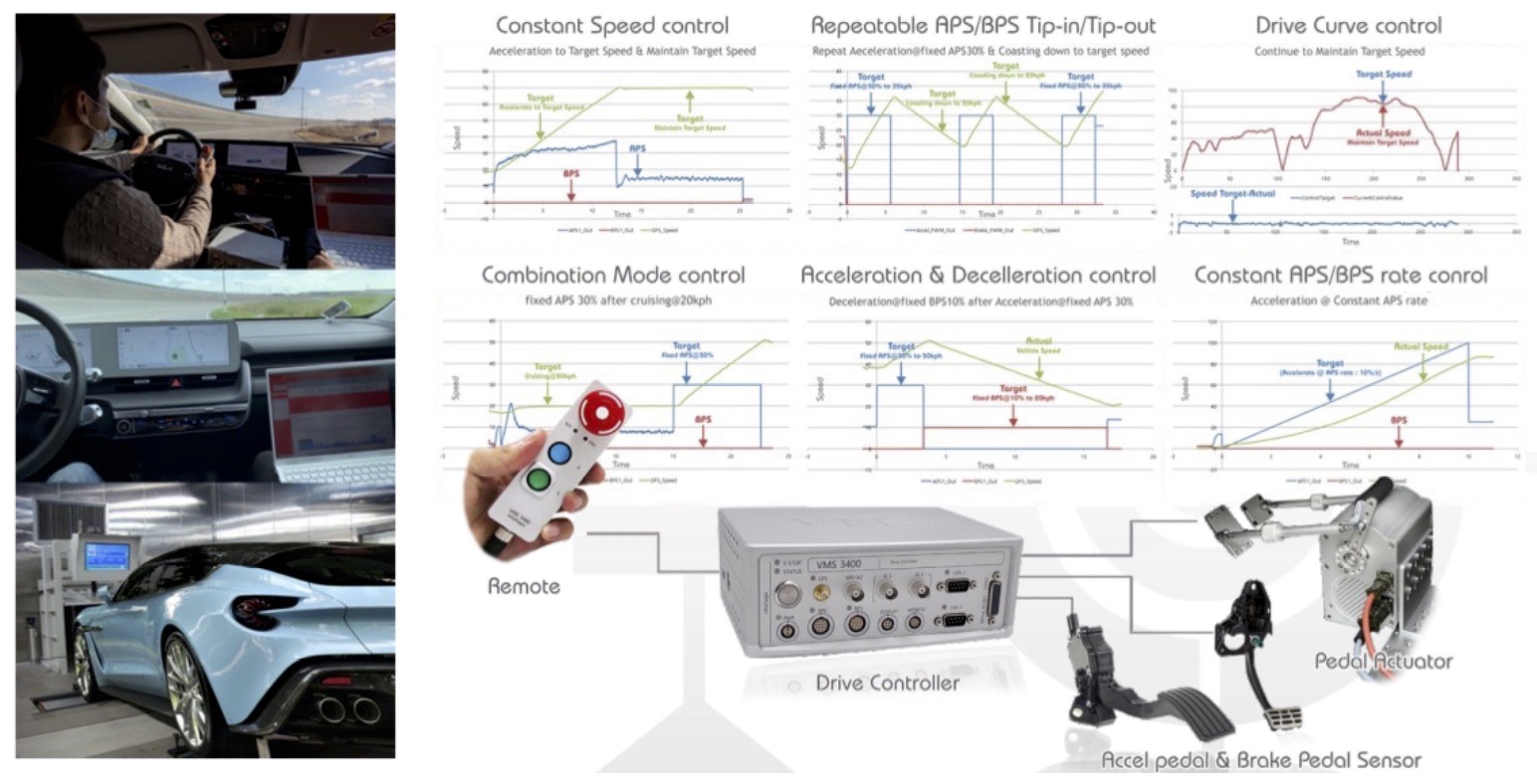
The VMS 3400 is a drive controller and drive performance measuring device with built-in 100Hz GPS and APS/BPS controller which replaces the role of the driver in controlling the accelerator and brake pedal.
The VMS3400 provides a typical APS/BPS connector and allows easy APS/BPS sensor connectivity, simplifying the test preparation and installation process.
The VMS3400 automatically performs tests according to test items, measures and stores data as the test progresses, and automatically classifies and manages test results data.
The driving controller can control the accelerator and brake pedals of the vehicle by simulating signals from the accelerator pedal sensor (APS) and brake pedal sensor (BPS) that are identical to the actual vehicle, thereby driving the vehicle. To start testing with the driving controller, first disconnect the APS/BPS cable connector from the vehicle pedal opening sensor to the ECU and connect it to the APS/BPS port of the VMS 3400.
Although the VMS 3400 is equipped with an APS/BPS controller and a 100Hz GPS, it only minimizes the device size by implementing necessary functions. The VMS 3400 can control the speed of the test vehicle. This function can be used to automatically drive the vehicle according to a pre stored driving curve, and the pedal robot can also serve as a driving robot for the speed controller of the test vehicle traveling on the chassis generator. The pedal robot provided by VMS 3400 is connected to VMS 3400 for automatic repetitive driving of previously stored driving curves. After installing the pedal robot, the driver can also manually operate it.
Drive Controller
Since the VMS3400 performs vehicle speed control by controlling APS/BPS signals, it is a perfect speed controller for chassis dynamo testing.
The VMS3400 can automatically control the "acceleration and brake pedal" according to the target speed, so it is a drive controller device that can precisely control the speed at a predetermined target speed and time.
The VMS3400 reduces the driver's speed control difficulties, maintains the best speed control, and improves repeatability.
The speed control function can be used on both chassis dyno and proving ground and allows the vehicle to run repeatedly according to a predetermined target speed. The same drive curve can be executed indefinitely.
The APS/BPS controller shows speed control in the full section. However, VMS3400 provides the option to use the Pedal Actuator to control the speed in the full section by using Accelerator and Brake Pedal control of the vehicle.
Vehicle performance test
As an automated vehicle performance test device VMS3400 is effectively applicable for automated performance test.As 100Hz GPS speed sensor and APS/BPS controller combined test device, VMS3400 is a device which can perform fully automatic and accurately repeatable tests.
High-performance controller VMS3400 offers real-time data collection performance and also the data analysis is being done with ActiveDC program to review test results.By automating the test procedure, VMS3400 minimized number of test equipment operation and after completionof test, result notification could be shown immediately.
Application features
All driving performance test conducted by this single device with 100Hz GPS speed sensor and APS/BPS controller.
Accurate repeatability test with very precise APS/BPS control. Greatly reduced Equipment operations by automated test procedure. Results can be checked immediately after completing the test.
Test application evaluations
Driving performance evaluation under various APS/BPS and BPS operating conditions
Acceleration and brake pedal on/off test
Constant Accelerator and brake pedal position control
Constant Acceleration and decelleration control
Accelerator and brake pedal rate control
Combination mode test
Speed control
Engine RPM control
Static DTV Tester
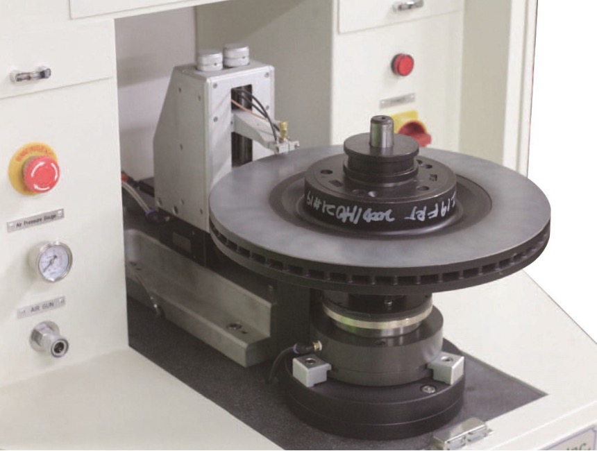
The DT-S is an automatic high-precision measurement system for Disc Thickness Variation (DTV) and Lateral Runout (LRO) of brake rotors. These conditions are the major causes of brake chatter/judder and can ultimately lead to premature NVH problems. The system provides the user DTV and Runout data in a three-dimensional imaging format, thus helping in investigation and analysis of geometric structure deformation caused by over-heating and excessive mileage on the brake rotor.
Features
1. The sensors scan the full surface of the friction part of the brake rotor with the selected track width automatically.
2. A precision air bearing spindle supports the rotor while an air bearing slide holds the capacitance sensors to keep accurate measurement for long lasting performance.
3. A universal fixture is used to minimize the need for multiple fixtures and easily accommodates a wide variety of rotor shapes and sizes.
4. Fixture accuracy check feature provides reliable measurement and maintenance.
5. Versatile analyzing software by “Sunware DT-S”
Analysis Software
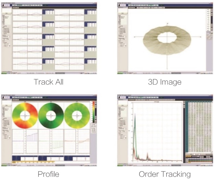
1. DTV, LRO for each track(s)
2. Variation traceable criterion options
3. Dimensional rotor image
4. Cross sectional rotor profile
5. Jig error correction with LRO
6. Order tracking by FFT
Specifications:
Adaptable Rotor Range | -Rotor diameter : 200-500mm (7.9-19.7”) -Rotor thickness : 5-55mm (0.2-2.2”) -Rotor weight : 30kg (166lbs) max |
| Sensor type | Capacitance |
| Measuring range | 0-1500 ㎛ |
| Spindle type | Air bearing |
| Rotation speed | 0-10RPM |
| Angular resolution | 16bit (1/65536) |
| Jig accuracy | 3 ㎛ or better |
| Air consumption | 50NL/min @0.4MPAS |
| Bench dimension | L750*W800*H800-1700mm (L29.5”*W31.5”*H67”) |
| Weight | 245kg (540lbs) |
Portable Brake Drag Tester
![]()
Portable Brake Drag Tester (DF-L) is a compact and light weight Brake Drag Force measuring system of the car on lift.
It rotate Disc CW/CCW direction and speed adjust while Drag Force measurement.
Measured data store and print out report at any revolution of wheel rotation by control & Analyzing software “Sunware DF-L”
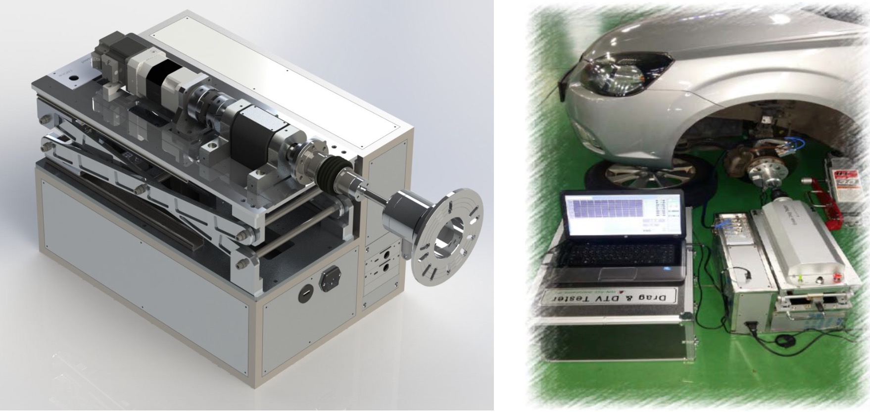
Features:
1. Variety speed control : CW/CCW, speed up/down
2. Non-contact precision torque sensor
3. Height adjustable bentch
4. Versatile analyzing software by “Sunware DF-L”
*DTV Test is possible by option

| Specifications | |
| Torque capacity | 75N.m |
| Sensor Linearity | 0.1%F.S |
| Rotation speed | 0~50RPM |
| softwares | Sunware DF-L |
| Size | W798 x D350 x H390 (mm) |
| Power Supply | AC220V 50Hz |
Vehicle DTV
The DT-V is a DTV measuring system of the vehicle. Non-contact type of capacitive sensor measure mounted lateral run out (LRO) and DTV in the car. Cold judder is measured in the off brake condition to investigate mounted lateral run out and DTV. Hot judder is measured while snap stop or one stop with high speed driving to investigate thermal deformation of rotor like corning and its behavior.
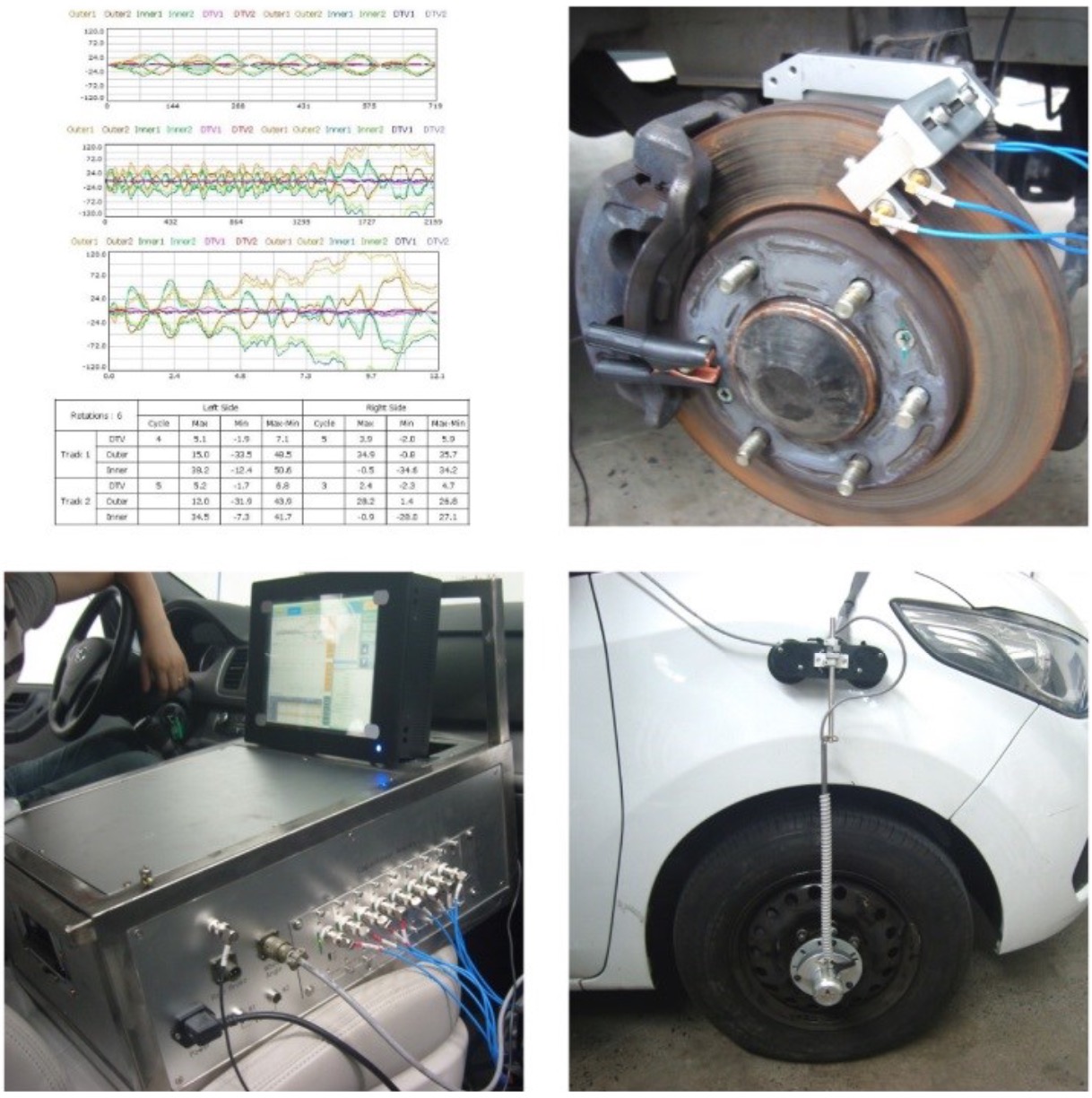
Features
1. Compact & robust sensor fixture.
2. Anti- vibration controller.
3. Time & wheel angle base sampling.
4. Manual or brake interlock trigger.
5. Versatile analyzing software by “Sunware DT-V”
| Specifications | |
| Measuring range | 0~2500㎛ |
| No. of sensor | 8 (2pairs each LH./RH) |
| Maximum speed | 180km/h |
| Sampling speed | 1Mhz |
| Date Resolution | 16bit |
Comprehensive Caliper Function Tester
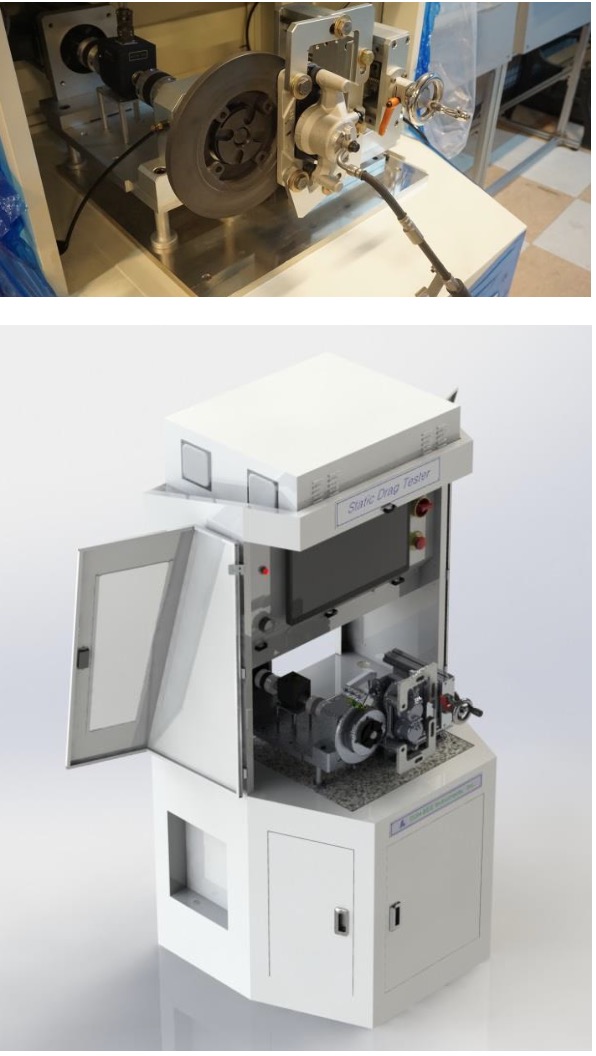
CFT-L is a comprehensive caliper function test system that evaluate performance and find defective factors. In pre-run stage it makes brake several times as per programed condition by Supplying compressed fluid. Fluid leakage and total flow together with Brake force are checked during the period. And then Drag Torque, DTV/LRO and any other factors performance tested recorded and displayed.
Features
1. Universal concept disc and caliper mounting fixture.
2. Friction free spindle bearing.
3. PC base speed, pressure control.
4. Non-contact type DTV/Runout sensors.
5. Precision digital torque sensor.
6. High resolution flow meter.
7. Versatile Analyzing software.(Sunware CFT-L)
Specifications
Speed Range(Accuracy) | 0 ~ 50 RPM(±1RPM) |
| Torque Range(Accuracy) | 0 ~ 12 N∙m(0.1% FSO) |
| DTV Range(Accuracy) | 0~2500㎛(0.2% FSO) |
| Flow Range(Accuracy) | 2~2000㎖/min(±0.3%RD) |
| Pressure Range(Accuracy) | 0~25㎫(±0.25% FS) |
| Air consumption | 50 Nl/min @ 0.6Mpas |
| Fluid capacity | 2L |
| Electrical power | 220V AC, 3A 1Ph |
CFT-L
Characteristic
1. High resolution torque test:
Friction free Air Bearing spindle support torque transmittal drive shaft between Torque sensor and caliper assembled disc to minimize rotational Resistance In the drive shaft. So that it can measure even very law residual Drag Torque.
2. DTV / Runout test
Non-contact type Displacement Sensors and flexible fixture helps easy test of DTV and Lateral Runout (LRO) of the Disc precisely.
3. Universal Disc & Caliper mounting Fixture
In order to accommodate various size and shape of disc and caliper, equipped universal concept of jigs and fixtures enable covering most of Common Disc & Calipers.
4. Brake fluid leak test
Embedded precision flow meter in Brake fluid supply line can measure fluid volume and define the fluid leakage in master cylinder.
5. Pinch force test
Pinch force of the caliper can be measured by the embedded force sensor.
6. Versatile Software
Measurement program offered test condition set up and display of Min/Max test values and tolerance discrepancy with warning signal during the test. Analyzing programs serve details in value distribution in cycle and statistical data and so on.
The test procedure of the CFT-L is as follows.
1. Power on the equipment PC and open the CFT-L measuring program.
2. Check the Brake Fluid level and if it is under the Lower mark, refill it.
3. Mount the Disc at the Drive Shaft end-The universal mount jig can adapt Diameter 200mm to 400mm of Disc.
4. Mount caliper at caliper mounting fixture it can moves x,y,z 3directions and tilt angle in accordance with the pad position.
5. Adjust the gap between disc and pad in caliper to secure running clearance of the disc.
6. Connect the Brake fluid supply pipe into the caliper inlet.
7. Bleeding the air in the master cylinder with push the pedal of fluid supply switch several times till air zero.
8. Click the “READY” button in the measurement program CFT-L and then select “FLOW CHECK” in the menu.-It begins to supply brake fluid into the master cylinder in accordance with sett pressure, duration, and cycles during the braking period, measure the pressure, total flow of the Brake fluid measured and define the fluid leakage phenomenon together with pinch force of the master cylinder.
9. Click the “START” then the drive shaft begin to rotate the disc and measure Drag Torque DTV and runout of the Disc. --- Prior to start, user have to select rotation speed, cycles.-For example, 50RPM, 10turns(cycles).etc.
10. Save the test data under the designated file name after clicking “STOP” and then finish the test.
11. Open the analyzing program(CFT-L Viewer) and the file names which want to investigate and analyze.
EPB-Endurance Test rig
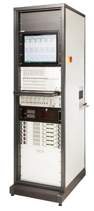
The test stand is designed for the endurance test of 12 electrical parking brakes (EPB).
The brakes are electrically controlled in pairs of 6 modules working independently of one another. Operation takes place via the modules or via an external control device.
The definition and transfer of the test program is carried out via PC Windows’s software.
Three separate hydraulic units enable the hydraulic control of three pairs of brakes.
Hardware
The hardware is contained in a 19" cabinet:
Front view:
- 19" screen to view the operating software / program status
- 6RU - placeholder for integrating measurement
instrumentation/signal conditioning
- Rack with 6 control modules and status display
- Keyboard slot with mouse repository
- 6 power supply units at 20V / 60A
- PC for operation and module communication
Internal:
- Cabinet ventilator with thermostat
- Switch for ethernet connection
- dSPACE- PC for CAN- Simulation
- Distributors with automatic circuit breakers
- Electrical brake connections
- 3 hydraulic units with brake fluid reservoirs, proportional valves,
pressure sensors and bleed pump
Left-hand side:
- Pneumatic supply
- Hydraulic circuit 1/3/5
- Connection recess
Right-hand side:
- Electrical mains switch
- Electrical supply
- De-aeration pump switch
- Warning lamp "re-fill brake fluid reservoir"
- Hydraulic circuit 1/3/5
- Connection recess
Operating Software EPB- Tester
It functions as the interface between user and control modules. It can be used to operate the brakes/ ECUs both manually and automatically by creating and transmitting endurance programs.
Similarly, the user can retrieve information about the current status of the program and view the values of the individual cycles via Plotter features.
The operator software includes different interfaces:
1、Editor
The editor contains all functions which are necessary to create a test program and to send it to the control modules.

2、Control Panel
The Control Panel enables the user to control the modules and to get an overview about the program status. A running test program can be controlled, and the user can actuate manually the brake and the hydraulic actuation.
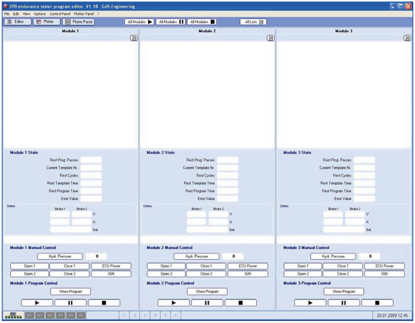
3、Plotter- Panel
The multi plotter control allows a total view about the electrical and hydraulic actuation of all active modules. On the right side of the plotter the momentary numerical values can be read.The measuring data in the plotter are updated with a frequency of 100 hertz.
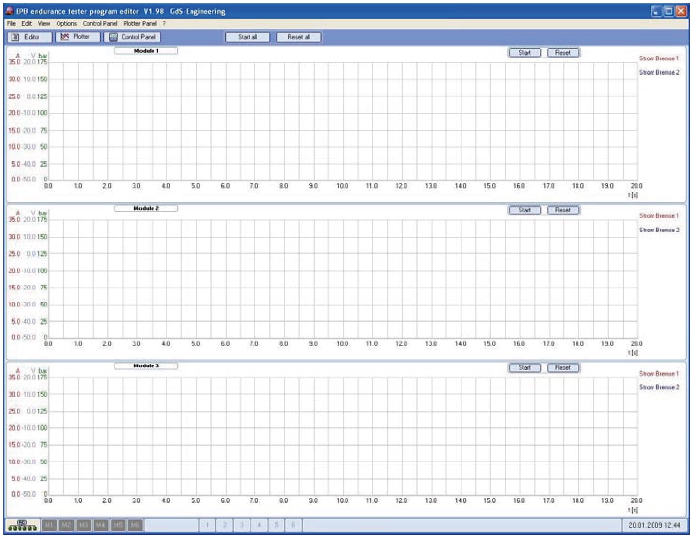
4、Plotter
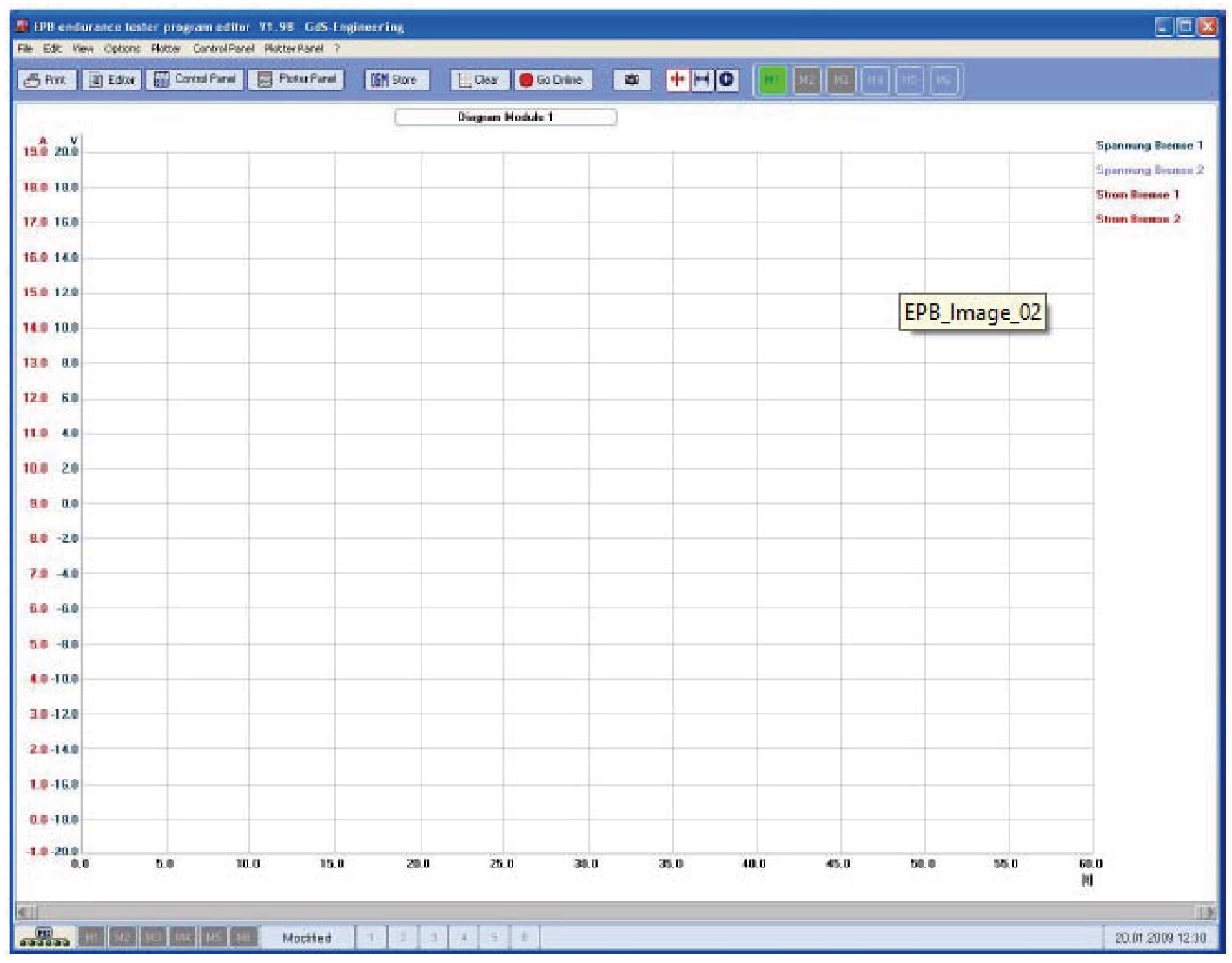
The (single-) plotter gives exact information’s about momentary values.
So e.g. an interim change of the No- load current can be controlled at
EPB Functional Test Rig II
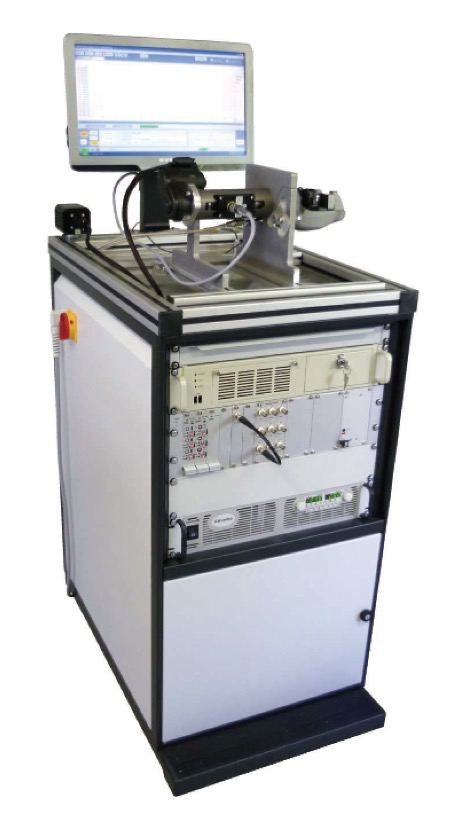
The EPB functional test rig is integrated into a mobile 19" cabinet. At working height, on one side a holding device is mounted for the EPB drive with motor and gear, and on the opposite side a holder for the brake is installed. The drive is connected to the brake via a torque measuring shaft. Thus torque is measured as well as speed and angle of rotation over a built-in incremental encoder. A load cell inserted in the brake is used to measure the clamping force. The motor is operated in 2 directions of rotation. The actuation voltage can be freely selected between manual and automatic mode. Voltage and current are also measured. The input power is calculated from voltage and current, the output is calculated from torque and speed. The efficiency of the drive is calculated from input and output. Taking into account spindle pitch, the efficiency of the spindle is calculated from the torque and the actual clamping force. Actuation of the device under test (DUT) is controlled by a µC on an external board that is located in the GdS-control module. Data exchange between PC and GdS-control module takes place over serial communication (RS232).
An actuation cycle consists of two phases:
ON-time during which the brake is closed or actuated until reaching the switch-off criterion (switch-off current or switch-off clamping force)
OFF-time during which the brake is released until reaching the release current, including follow-up time.
The operating software "EPBPerformance.exe" performs following tasks:
• Control of the operating voltage, current limit and the hydraulic pressure over D/A outputs of the National Instruments PCI 6229 controller card.
• Control of the drive, clamping and release via the GdS-control module.
• Switch-off in case of definable current or external signal (clamp force).
• Calculation of the angle of rotation by increment of the incremental encoder signals including
• Calculation of speed by edge distance measurement, including direction of rotation.
• Calculation of all performance levels and efficiencies (drive, spindle), see section 1.3.
• Visualization of data in different graphs in the plotter.
• y/t graphs with all measurement channels and calculated sizes, channels can be faded out.
• x/y graphs, all channels can be selected as x-axis, y-scales can be faded out.
• Storage of all measured values and calculated values including a header that comprises specific data of the DUT, inspection time and tester, in a Lucas data file ("*.LDFII").
Hardware
phases:
• Schroff 19" cabinet, worktop at about 1050 mm with holder for DUT.
• Cradle for quick changing of the DUTs.
• Monitor, keyboard and pull-out mouse pad recessed in drawer.
• PC, 2.8 GHz, with National Instruments PCI 6229 M-Series measurement and control card and CAN card.
• TRW signal conditioning max. 18 channels, 3xDMS, 3xISO, 3xTemp
• Power supply, 40 Volts (or 20 Volts), 70 Amps.
• 200 bar pressure transducer with prop. valve and pressure sensor
• GdS-control module comprising control with Hall signal conditioning and actuator temperature measurement.
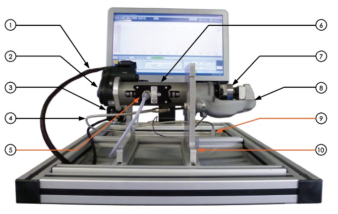
1—Cable harness for EPB actuator (motor).
2—EPB actuator, motor and gear (DUT).
3—Socket to connect the actuator (electrical).
4—Brake line for connecting the DUT (hydraulic).
5—Plug to connect the torque sensor.
6—Measuring shaft for torque, speed and angle of rotation.
7—Load cell (clamp force measurement).
8—EPB brake (DUT).
9—Port for the EPB brake (hydraulic).
10—Holder for the EPB brake with motor and gear.
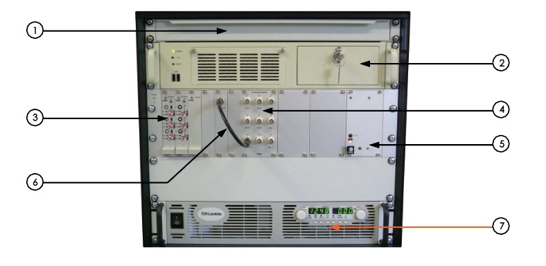
1—Drawer for keyboard and mouse.
2—Industrial PC with operating system Microsoft Windows XP Professional.
3—TRW signal conditioning.
4—BNC - outputs for all analogue measurement channels.
5—Power supply unit for all test components (sensors, proportional valves ...).
6—BNC connection cable of analogue measurement channel for clamping force with the external signal input of the GdS-control module (for switch-off over clamp force).
7—Power supply, 40 Volts (or 20 Volts), 70 A, for supply of the EPB actuator.
Engine Tachometer
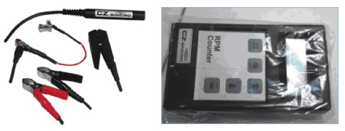
The DB4 engine tachometer can measure engine speed on any model of gasoline and diesel engine, 2-stroke or 4-stroke, single cylinder to 12 cylinder. If the measurement is taken from the vehicle battery, the number of cylinders ranges from 1 to 8.
Measurement can be carried out through the following methods:
◆ Sensor cables collect vehicle battery signals;
◆ Photoelectric sensors and reflectors are installed on diesel and gasoline engines, pulleys, and other rotating components;
◆ The induction clip is clamped on the ignition coil with a distributed ignition system;
◆ Piezo is clamped onto the diesel engine injection pipe;
◆ Induction pliers are used for high-pressure common rail engines.
Car Roll Cage
This titanium alloy roll cage complies with the regulations of the National Highway Traffic Safety Administration (NHTSA-2001-9663) document in the United States. Its purpose is to effectively prevent car rollover accidents during turns or other emergency situations. Its advantages are simple structure and easy use, making it an ideal protective device for preventing vehicle rollover. There are three models to choose from: light, standard, and heavy.
