Vehicle dynamic robot
Turning robot
The steering robot is controlled by a computer and performs precise and repeatable measurements by applying inputs to the vehicle's steering system during road tests. Steering robots have been widely used worldwide, with over 1350 systems in use. The main applications include vehicle dynamic testing and steering system development, but many customers still use its path following function to conduct experiments unrelated to the steering system. The maximum torque of the steering robot motors we provide can reach 150Nm. The standard models for typical testing are SR30 and SR60, which provide rated torque outputs of 30 or 60 Nm. The robot with the highest torque is the SR150, which can also be tested when the power steering of trucks or buses fails (certification testing is a typical application).
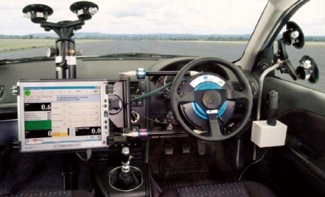
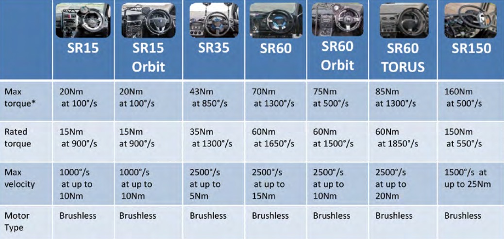
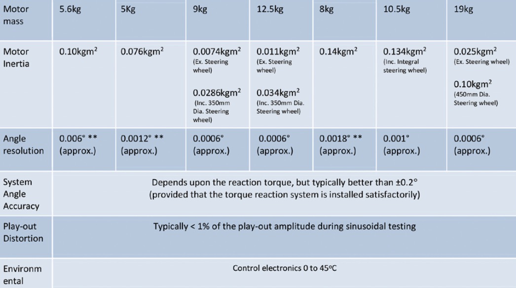
Performance specifications for steering robots:
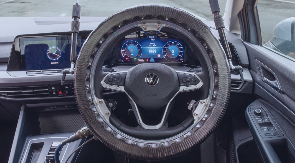
Halo Turning Robot
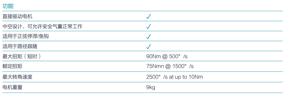
The Halo robot is a direct-drive hollow centre steering robot that enables a wide range of steering inputs to be applied with high precision and repeatability, so that high quality data can be captured.
Halo uses a low friction coefficient direct drive motor and lightweight shell material, making it the smallest hollow ring steering robot in the market in terms of rotational inertia and friction. Compared with the SR60 Torus, Halo's rotational inertia is reduced by 8.5%, and its open ring friction is reduced by 30%. Compared with the hollow ring steering robot SR15/60 Orbit constructed by a gear driven motor, Halo is even more impressive. It also retains the advantage of a hollow annular motor - it allows the airbag to deploy normally. It is an ideal choice for current common testing standards, including handling stability, ESC, AEB, ADAS, Euro NCAP Emergency Steering Support (ESS).
Technical parameter
Common control modes:
◆ Steering wheel angle control; ◆ Steering wheel torque control.
Installation method:
◆ Direct installation (installed on the steering column of the vehicle);
◆ Indirect installation (installed on the steering wheel of the original car through an adapter).
(Note: Ring motor SR15, Torus, Orbit can only be installed on top or back of the steering wheel)
Standard test template:
◆ SR Continuous Sine
◆ SR Tyre Conditioning
◆ SR General Trapezoidal
◆ SR Parking Effort
◆ SR Kerbing
◆ SR Returnability
◆ SR Periodic Random Noise
◆ Path Following test(Option)
◆ SR Spin-out(sinusoidal)
◆ SR Linear Sweep
◆ SR Square Step
◆ SR Roll Stability
◆ SR Catch-up
◆ SR Derating
◆ SR Constant Level
◆ Learn test
◆ FMVSS126 test group
◆ SR Spin-out(const velocity)
◆ SR Const Vel Sweep
◆ SR Trapezoidal Step
◆ SR Pulse
◆ SR Slowly Increasing Steer
◆ SR Flick
◆ SR External follow
◆ SR Periodic Random Noise
◆ Regulation 13-H test group
Torque reaction mechanism:
1. Standard type: includes torque measurement, with the best driver visibility and the most secure installation.
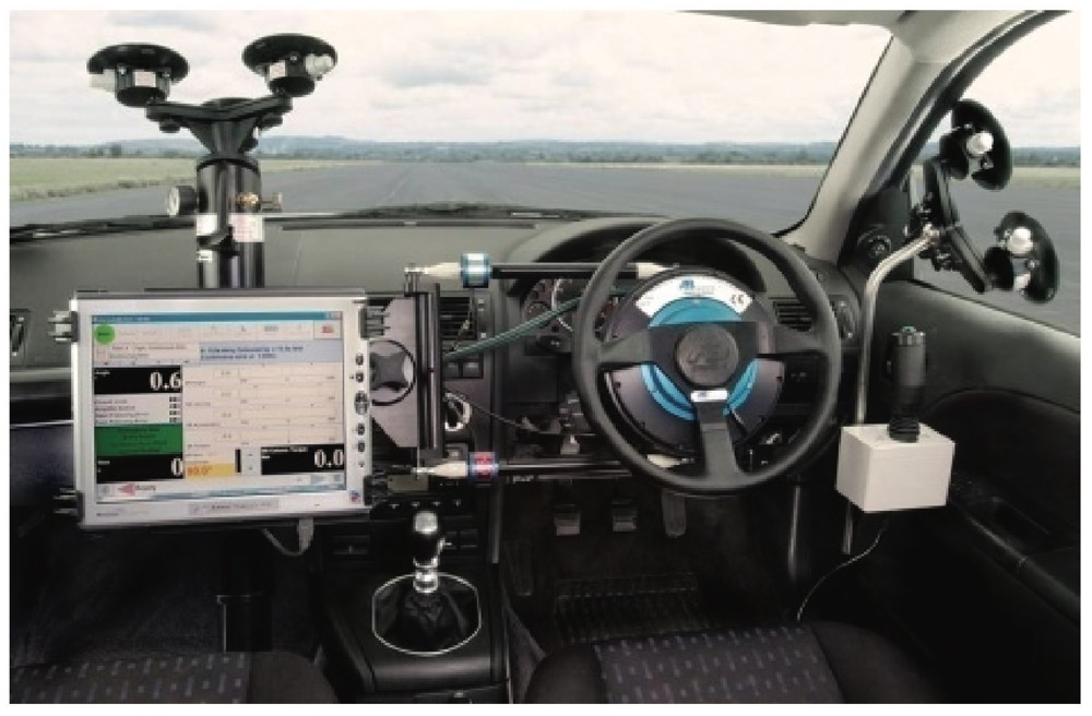
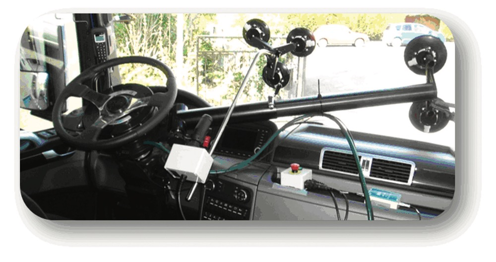
2. S-type installation: direct windshield installation, simple, fast, and inexpensive, without torque measurement sensors [can be estimated by motor current or cylindrical torque sensors can be installed (only SR30, SR60, SR150 for direct installation)].
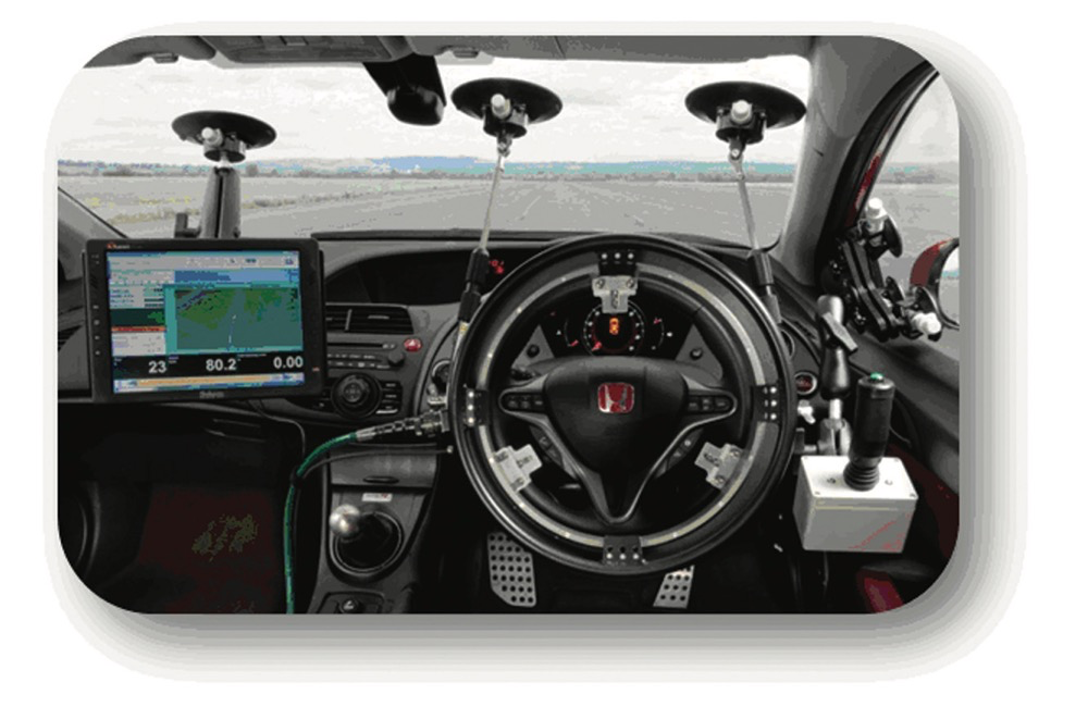
3. TD type torque reaction: installed on the passenger seat bolt without torque measurement sensor [can be estimated by motor current or cylindrical torque sensor can be installed (only for direct installation SR30, SR60)].
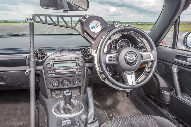
4. SR150 windshield mounting arm: specifically designed for SR150, without torque measurement sensor (can be estimated by motor current or installed with cylindrical torque sensor).
Path following function of turning robot:
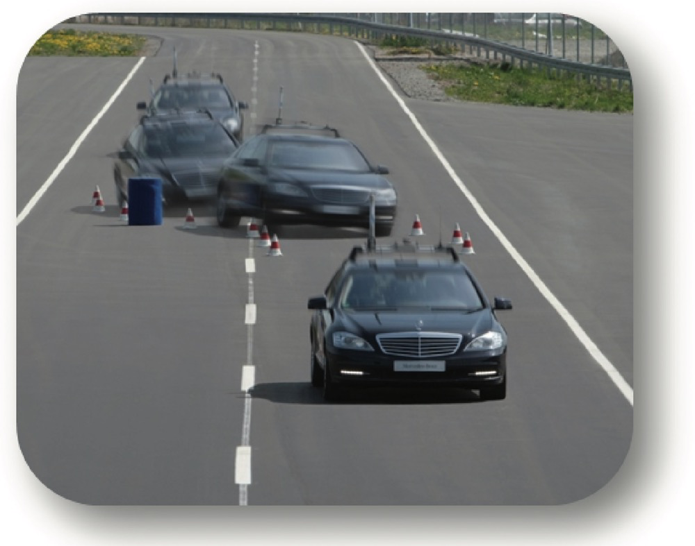
By combining the steering robot with an inertia motion package with GPS correction, the steering robot can be used to guide the vehicle along a set path, achieving the function of path following. If DGPS is used to correct motion packets, a path following accuracy of 2cm can be achieved. Mainly used to improve the accuracy and repeatability of the test path, it is commonly used in obstacle avoidance tests, such as circular tests for oversteer or understeer, ISO double lane change tests, snake shaped tests, closed-loop loop timing tests, etc. The maximum path following speed can reach 220KM/H.
Path generation method:
◆ Learn a path through manual driving, and then create this path through recorded data
◆ Use the geometric line segments in the path generation software module to draw the required path step by step;
◆ Create a path from raw ASCII data.
Braking robot
The brake pedal robot applies input to the vehicle's brake pedal and can perform precise and repeatable measurements during road or laboratory testing. The design of the system enables the vehicle to drive normally and safely after installation. Robots are suitable for use on cars and trucks.
Brake pedal robot control mode:
◆ Position control, feedback provided by sensors on the actuator or directly connected to the brake pedal;
◆ Force control, feedback provided by a force sensor that measures braking force;
◆ Deceleration control, feedback provided by acceleration sensors that can measure vehicle deceleration;
◆ Brake pipeline pressure control, feedback provided by the brake pipeline pressure sensor;
◆ Speed control of auxiliary accelerator pedal robots.
Classification of brake pedal robots:
BR1000(on seat)
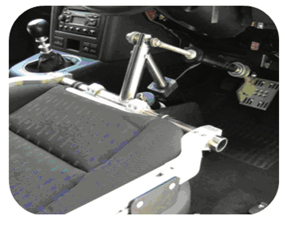
2. BR1000(under seat)
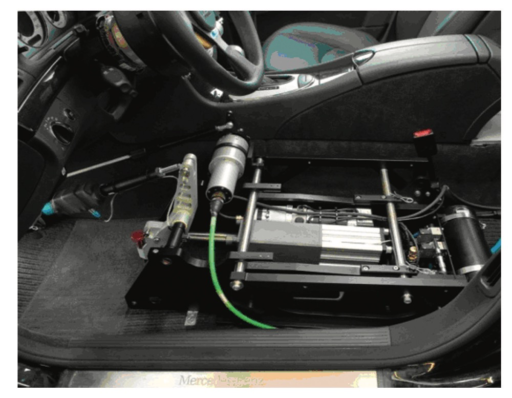
3. CBR600L/CBR600
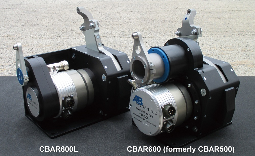
4. RBR1500
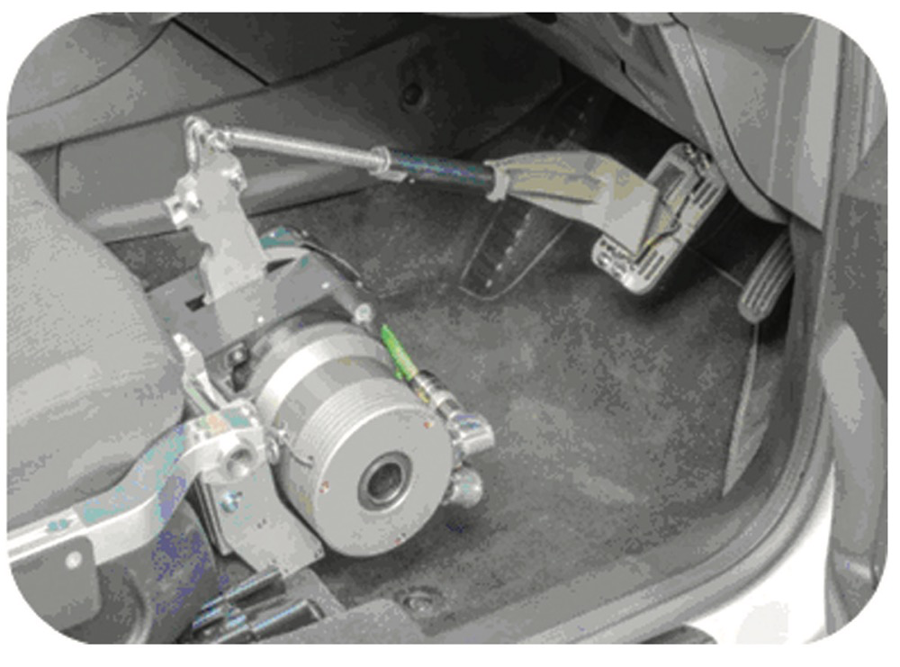
5. CBAR1000
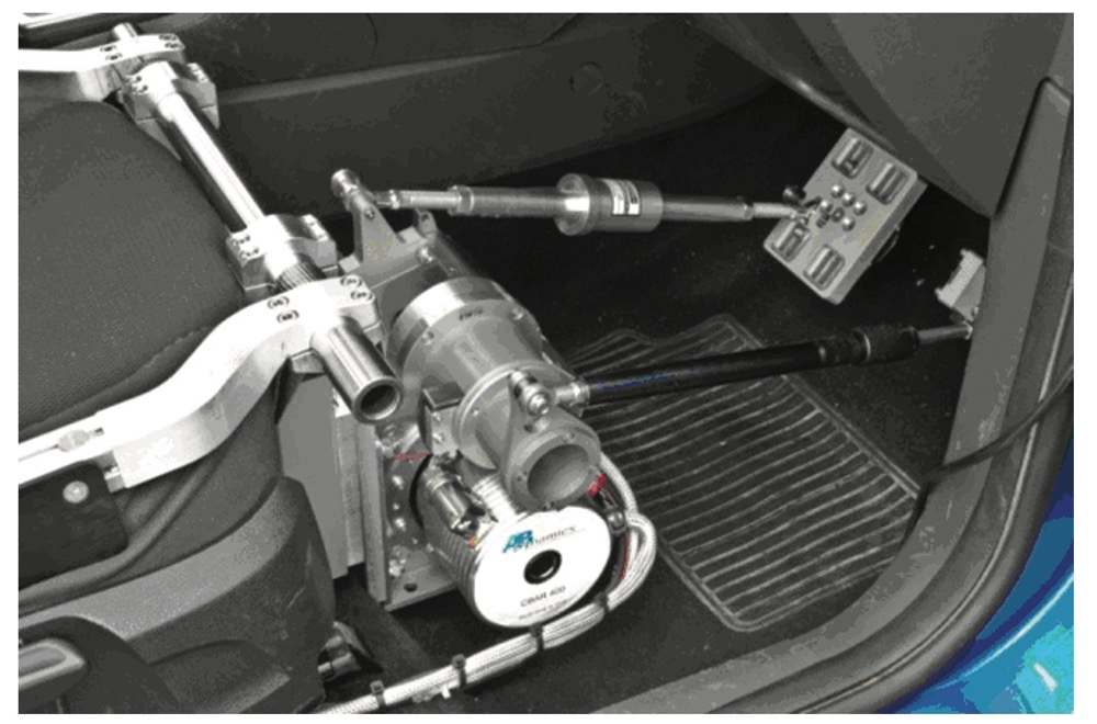
Performance specifications for braking robots:

◆ Easy to install on most car models - no need to drill holes in the car;;
◆ Install the actuator on an adjustable seat frame or driver's seat rail;
◆ After installing the braking robot, the vehicle can still be driven manually normally;
◆ Can be used in conjunction with steering robots;
◆ Pedal travel can be measured through high-precision encoders;
◆ It can measure braking force (there are two optional force sensors).
Standard test template:
◆ BR Trapezoidal Step test;
◆ BR Ramp Triggered Hold test;
◆ BR Triggered Mode Change test;
◆ BR User Defined test;
◆ BR External Follow test.
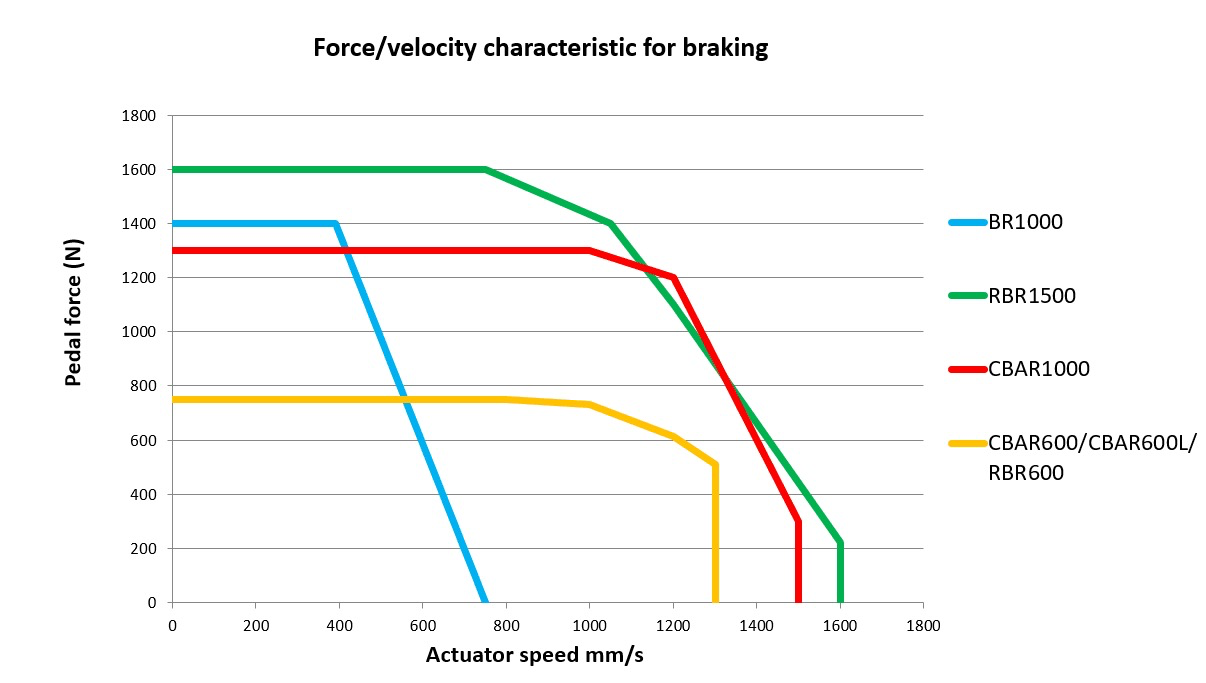
Accelerator pedal robot
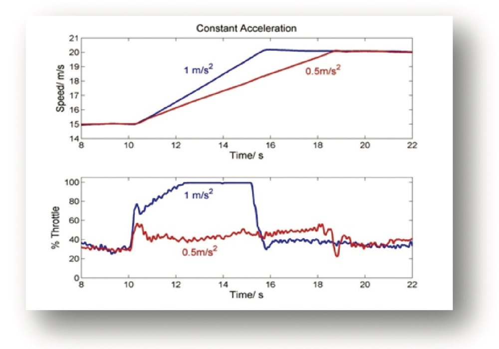
The precise control of the accelerator pedal provided by the AR1 accelerator pedal robot enables precise control of vehicle speed. AR1 can be used in combination with steering robots and brake pedal robots. However, it can also be used separately in situations where precise control of vehicle speed is required. For customers who require simultaneous braking and throttle input, they can consider whether CBRA or individual braking and throttle pedal robots are closer to their actual applications. When combined with a path following steering robot, the accelerator pedal robot can control a variable speed along the path, but of course, it cannot slow down the vehicle faster than the usual situation of coasting with the accelerator closed. If greater deceleration needs to be controlled, the assistance of a braking robot is required to achieve perfect speed control.
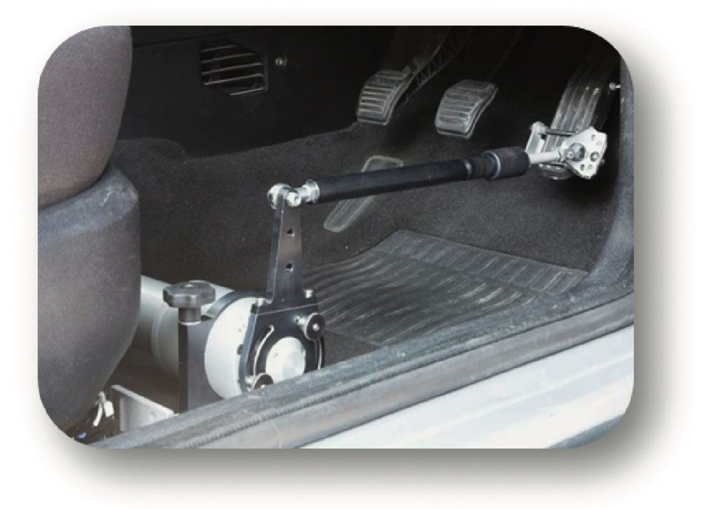
Accelerator pedal robot control mode:
◆ Accelerator pedal position control;
◆ Vehicle speed control.
Performance specifications:

◆ Using electronic rotary motors;
◆ Installation is very simple and fast;
◆ Install onto the seat rail (or attach to the seat mounting frame of BR);
◆ The driver can drive the vehicle normally;
◆ It can be used in combination with steering robots and brake pedal robots;
◆ It can be compatible with various speed feedback sensors: GPS, five wheel tester, wheel speed encoder, speed data on the vehicle's CAN bus, etc.
Standard test template:
◆ AR Speed Throttle Event test;
◆ AR User Defined test;
◆ AR Trapezoidal Step test;
◆ AR Constant Level test;
◆ AR External Follow test;
◆ AR Clutch bit test.
Shift robots and clutch robots
Gear shifting robots and clutch pedal robots are mainly used for unmanned driving testing of manually shifting vehicles:
◆ The shift robot has two motors for X-Y direction control of the shift lever.
◆ Gear shifting robot with optional single motor, mainly used for gear shifting control of automatic transmission vehicles.
◆ There are two types of clutch robots available for use in conjunction with CBAR or BR/AR.

Gear shifting robot performance specifications:
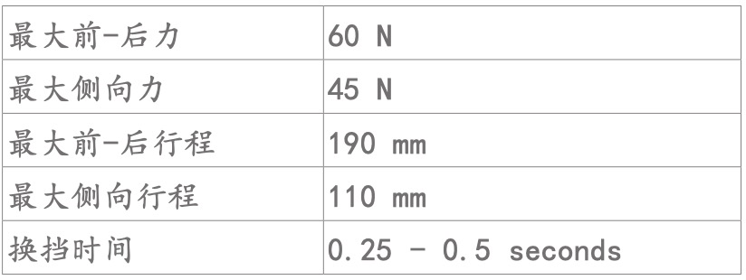
Performance specifications for clutch robots:

Unmanned driving test system
Since 2008, we have integrated a series of existing steering robots, brake pedal robots, accelerator pedal robots, clutch/shift robots, and path following functions to develop an unmanned driving testing system, mainly applied to vehicle dynamic testing, ADAS advanced driving assistance system testing, abuse testing, durability testing, and other testing applications. Realized unmanned driving testing that completely eliminates the need for drivers on the vehicle, reducing the risk for testers.

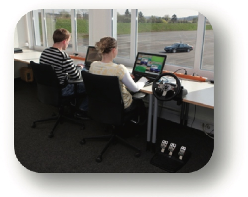
Equipment required for DTS:
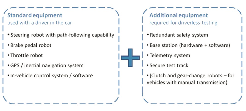
◆ The vehicle is controlled by a remote base station installed on the edge of the test track (which can be inside a parked vehicle or a building);
◆ The experiment can start with remote base station setup and control;
◆ Vehicles can be remotely controlled from the base station through a PC game console;
◆ The base station provides a failure protection emergency stop system.