Automobile three-pedal performance test scheme
System introduction
The GA-13 automobile clutch pedal performance test system is an intelligent automobile pedal test equipment independently developed and developed based on pedal stroke calculation, which can realize the test of the stroke trajectory and pedal force of the clutch pedal of various types of vehicles. The instrument adopts the data acquisition system as the main control core, selects the imported pedal force sensor and rotation angle sensor as the main test components, transmits data through the CAN bus interface, and is equipped with professional operating software, which can be displayed and saved on the host computer in real time.
The system conforms to the ergonomic mechanical structure of automobiles, and the whole inspection process is convenient and fast. It is an ideal testing equipment for automobile manufacturing industry, automobile maintenance industry, automobile testing and scientific research departments.
System range and accuracy
| The main technical parameters | |||
| No. | Description | Test Range | precision |
| 1 | Test stroke | 0~250mm | <0.3%FS |
| 2 | Pedal forc | 0~500N | <0.1%FS |
Note: 1. The sensor range can be customized; 2. The actual test accuracy will vary depending on the sensor range.。
System Features
The complete system is easy to install and easy to use
Windows Chinese operation interface setting and analysis software, easy to use
Various measurements or collected data can be displayed in real time
The system components and wiring harness are connected reasonably and are easy to use
Various test conditions can be set for testing according to requirements
High precision, high reliability, high vibration resistance and shock resistance ensure test quality
The system has a high degree of scalability, which can be extended to connect to various other sensors or test systems
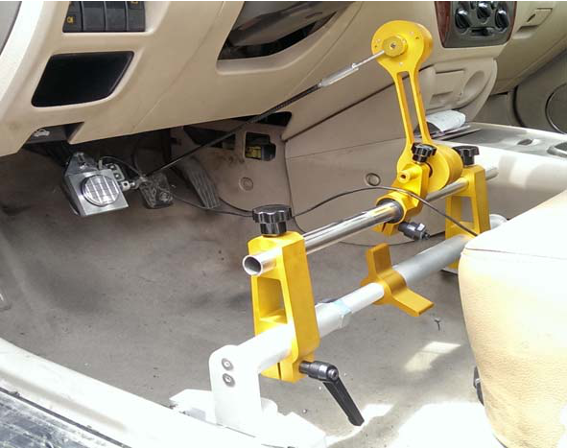
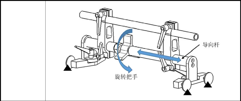
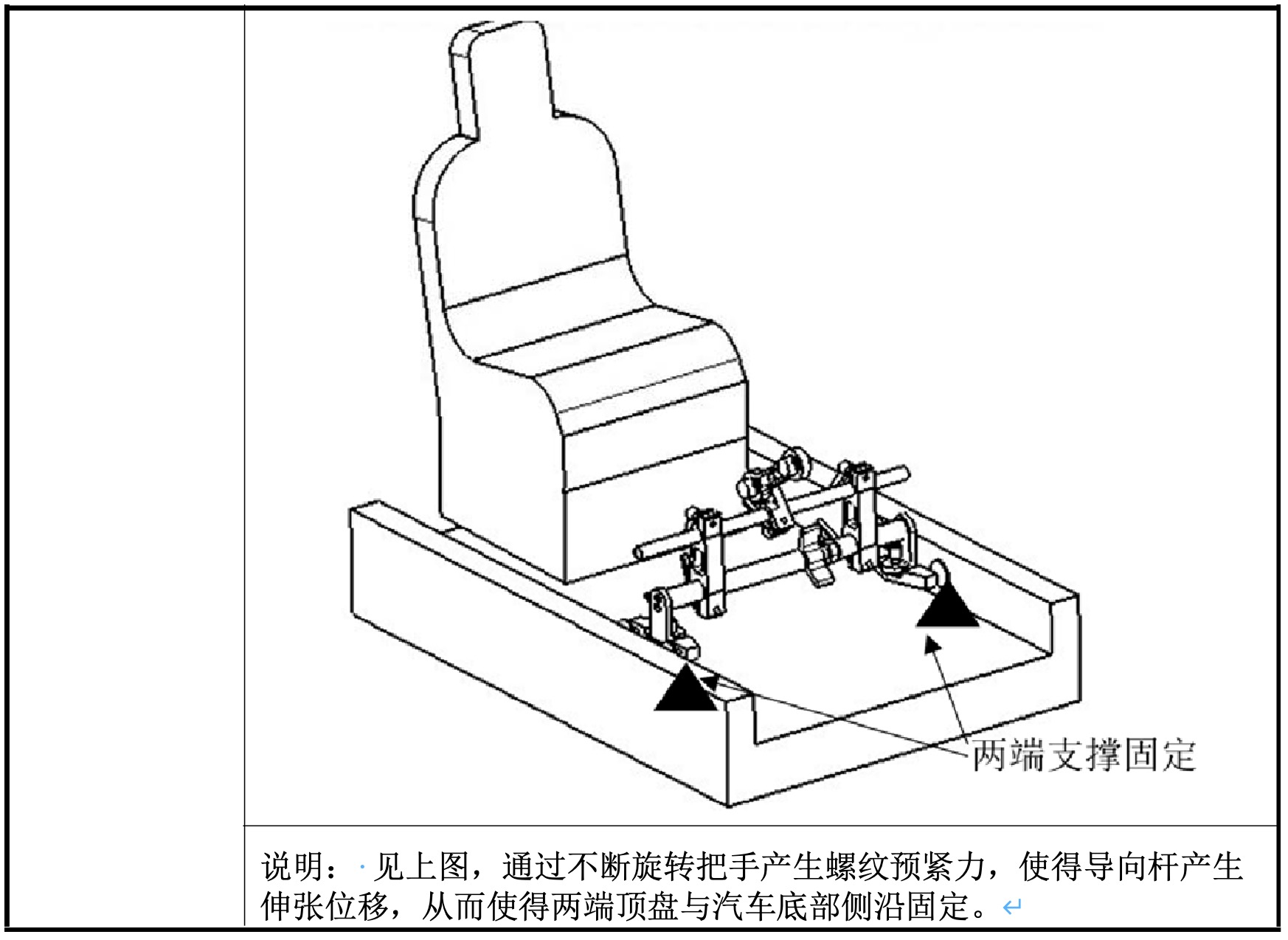
Pedal fixing bracket
1. The principle of fixing
Options for pedal displacement measurement
1. Measurement principle
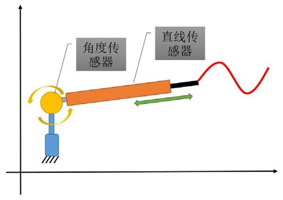
As shown in the figure, the measurement module composed of an angle sensor and a linear displacement sensor can measure the space vector curve data in real time. The system adopts the relative quantity calculation method (before measurement, the system automatically resets to zero), so the test result has nothing to do with the installation position of the sensor. It is only necessary to ensure that the sensor arrangement plane is consistent with the pedal trajectory plane.
During the test, the data acquisition system obtains the angle and displacement change in real time, and sends it to the host computer for data calculation and display.
The data acquisition system collects the pedal variation information in real time and point by point, and finally obtains the pedal motion trajectory through calculation.
System software
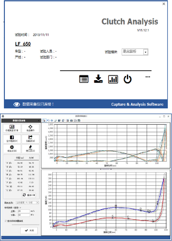
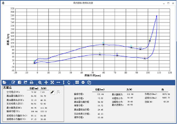
Test items
When this device is used for vehicle pedal test, it can record the process of stepping on the pedal in real time, and automatically store the pedal force-travel curve data. The system software automatically analyzes key points according to the data collected by the test, and the calculation results can directly generate report documents.
Generally speaking, the curve data recorded during the pedaling process is divided into upper curve and lower curve. This is due to the internal damping of the pedal system, which causes the two curves to not coincide, that is, pedal hysteresis.
1. Clutch pedal
T e s t l e g e nd | 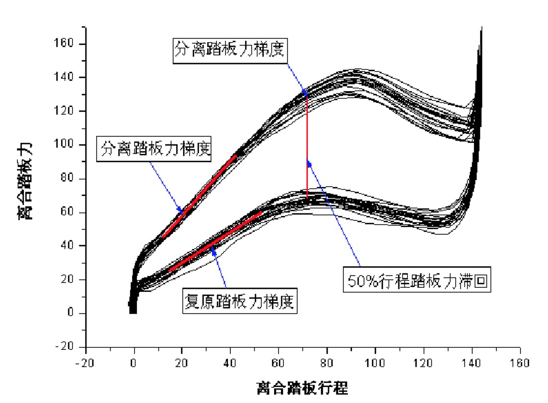 |
| Key points and parameters |
|
2. Accelerator pedal
| Test legend | 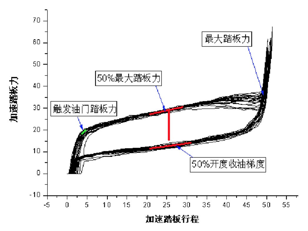 |
| key parameter |
|
3、Brake pedal
| Test legend | 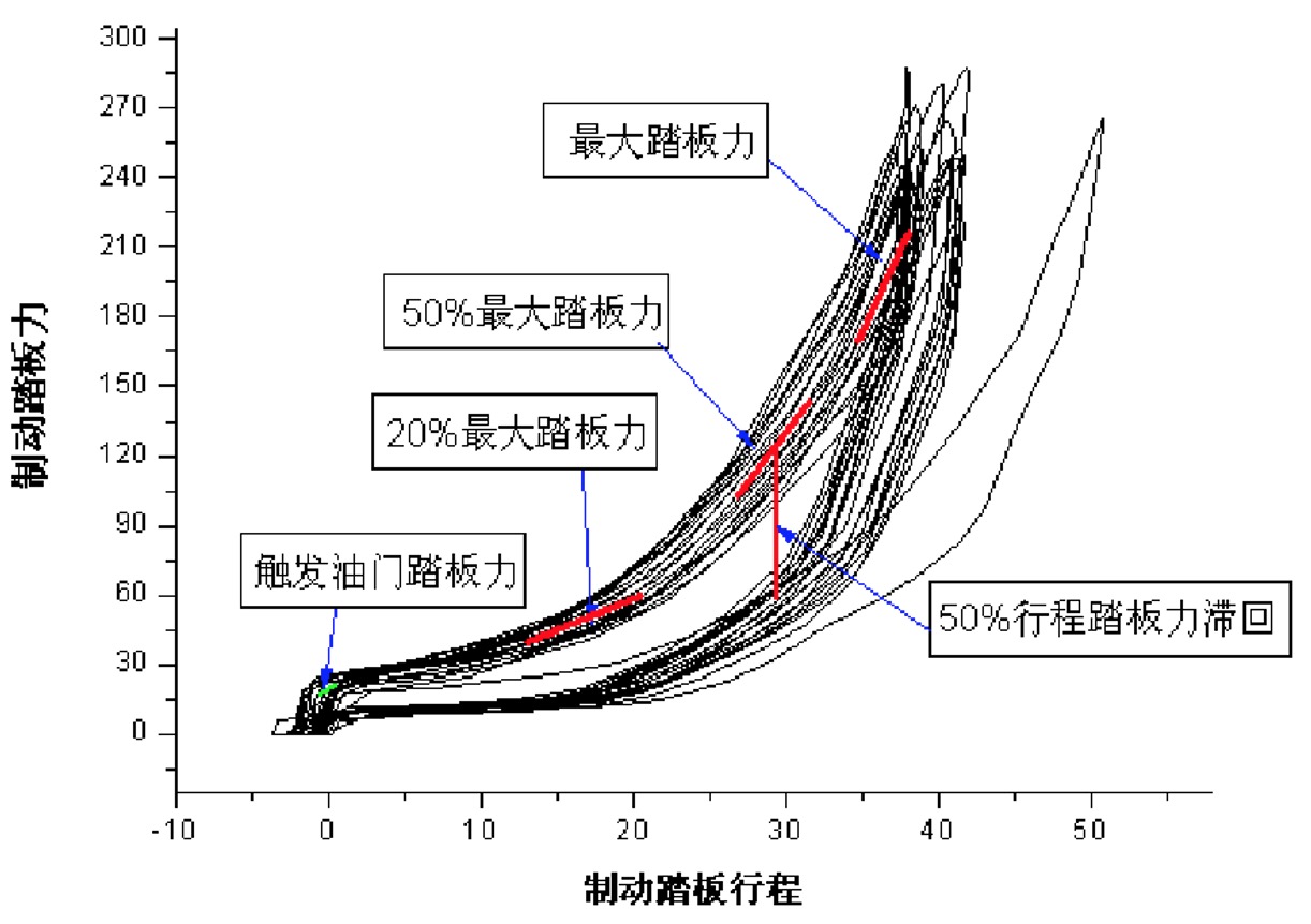 |
| key parameter |
|
Configuration and accompanying item list
| serial number | Name | Qty | Function | Specification | Remarks |
| Basic module | |||||
| 1 | Equipment fixing tooling | 1 set | Used to fix the measurement system to meet the needs of each test | Type: Integral bracket tooling (displacement solution) Installation method: meet the installation method that does not damage any parts under the design state of the whole vehicle Test object: The test of the force and stroke of the parking brake operation (handbrake) system and the brake pedal can be completed under the design state of the whole vehicle Carrying method: mass ≤5Kg, portable | Tooling can be customized |
| 2 | Data acquisition system | 1 set | Connect the sensor for communication and data collection, analyze and process the collected data, and output the collected data | Operating temperature range: ‐10~+55 ℃ Power supply overvoltage protection: ≥24V Analog signal channel: ≥4 channels (external modules can be connected); Measurement type: voltage, current, bridge, strain sensor; Resolution: ≥16 bits; Sampling frequency: ≥1000Hz. | Brand and specification optional |
| 3 | Pedal Force Measurement Module | 1 set | For vehicle pedal force information measurement | Measuring range: 0~1000N Accuracy: ≤0.5% F.S Working temperature: ‐10~55℃ Maximum overload: ≥150% Signal line: ≥3m Easy to assemble and disassemble, stable installation, does not affect normal driving after installation, can be used alone | Brand and specification optional |
| 4 | Pedal force display | 1 | Real-time display and storage of data without connecting data acquisition systems and laptops | Power supply: 9‐12V DC Output signal: 4‐20mA or 1‐9mA Cable length: 3m | Brand and specification optional |
| 5 | System software | - | Realize the collection of test data | Solve, dynamically display, and archive real-time acquired data Curve properties can be arbitrarily defined The software provides zero point correction function to ensure test accuracy Highly scalable. Through software settings, it can be connected to various test systems and sensors Synchronous sampling of defined channels Full Chinese interface Support data statistical analysis | No user node constraints |
| Displacement settlement measurement module | |||||
| 1 | Angular displacement sensor | 2只 | It is used to measure the rotation angle of the pedal measurement arm, and the final solution is the displacement. | Type: Potentiometer Type Measuring range: 0°~300° Independent linearity:<0.1% Repeatability: ≤0.01% | Standard |
| 2 | Linear displacement sensor | 1 | Used to measure the displacement of the pedal in the stretching direction | Structural form: potentiometer type Measuring range: ≥200mm Independent linearity:<0.1% Working temperature: ‐20~80℃ Signal line: ≥2m | Standard |
| Other optional modules | |||||
| 1 | Handbrake force measurement module | 1 | Can measure handbrake force, handbrake rotation angle | Measuring range: 0~1000N Accuracy: ≤1% F.S Working temperature: ‐20~55℃ Maximum overload: ≥150% Signal line: ≥3m | Two models are available (whether angle can be measured). |
| 2 | Handbrake force display number | 1 | Real-time display and storage of handbrake test (force and angle) data without connecting a data acquisition system and a laptop | Number of channels: 2 Power supply: 9‐12V DC Output signal: 4‐20mA or 1‐9mA Cable length: 3m | Single and dual channel available |
| 3 | Brake Line Pressure Measurement Module | 6 | It can test the pipeline pressure of two main oil circuits and four branch oil circuits | Pressure range: 100‐1000mbar Overpressure: 150%FS Excitation: 5V DC Nonlinearity:<0.5%FS Repeatability: 0.05%FS Response time:<20ms Long-term stability: ±0.1%FS/year | |
| Other | |||||
| 1 | Accessories and packing boxes | 1 set | Effectively store and protect the test test system, easy to carry. | 200KG compressive capacity | LOGO customizable |
Note: 1. The * mark indicates the necessary configuration. 2. The sensor specifications are recommended indicators. For more accurate indicators, please refer to the specific brand sensor specifications.
Applications
| Content | Physical map | Illustrate |
Installation and fixing of pedal force sensor | 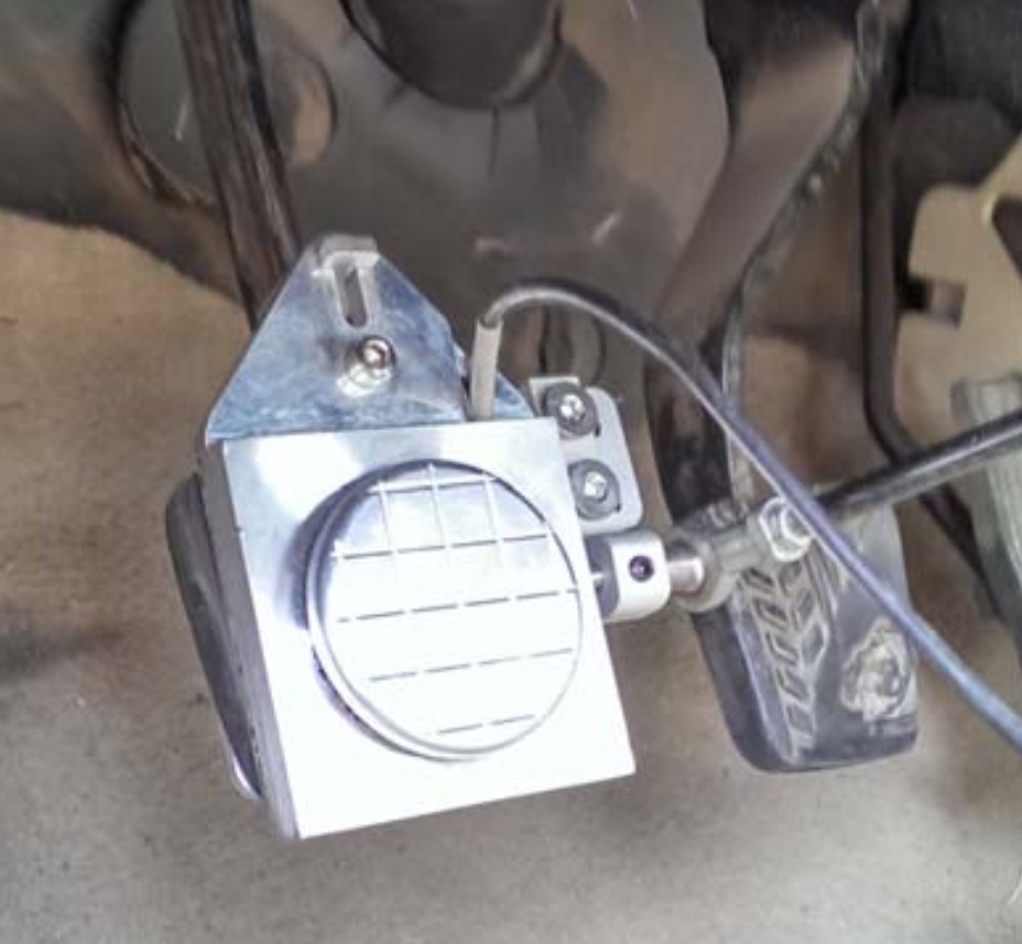 | The lightest and thinnest pedal force ensures high-quality test results. Various types of fixtures can be customized for different pedal types (free of charge). The displacement measurement point defaults to the center of the pedal plane. |
Lateral space for pedal fixing support fixture | 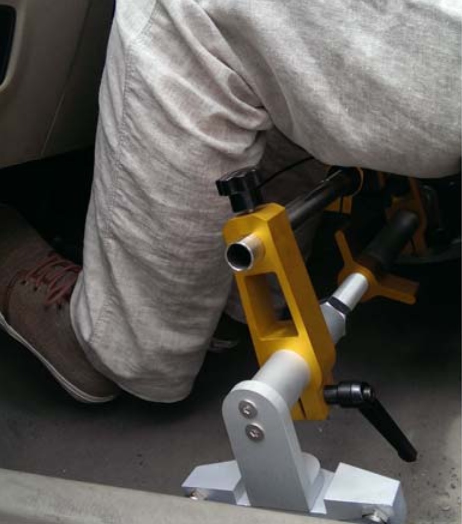 | The pedal clamp installation can be adjusted up and down, and the fixed state does not interfere with the tester's legs. |
Pedal fixing support fixture looking down space | 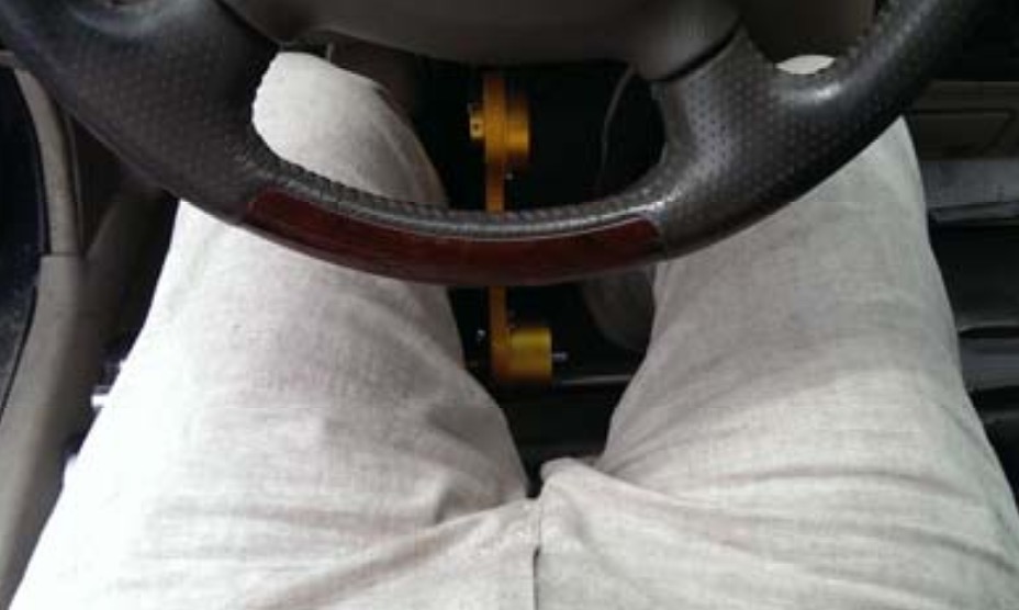 | The pedal fixture installation can be adjusted left and right, and the measuring arm (mechanism) does not interfere with the tester's legs during the test. |
The equipment mainly meets the standard
This test system is used to test the pedal operation force and stroke of automobiles, and can meet the test requirements of the following national standards:
GB 7258-2012 Technical conditions for motor vehicle operation safety
GB 21670-2008 Technical requirements and test methods for passenger car braking systems
GB 12676-1999 Structure, performance and test method of automobile braking system
GB 12543-1990 Automobile acceleration performance
Introduction of electrical components
1. Data acquisition instrument
| Exterior | 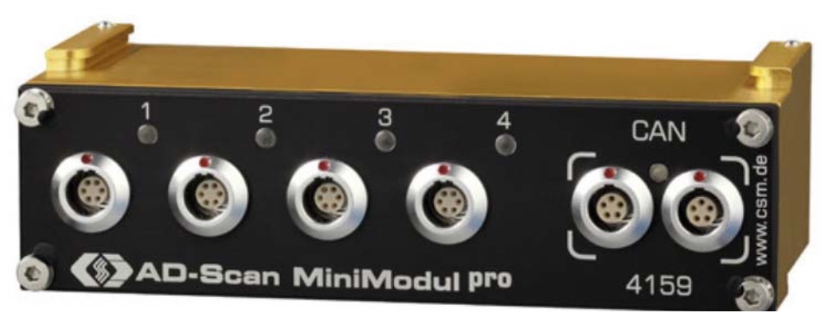 |
| Tooling and Dimensions |  |
| Electrical connection | 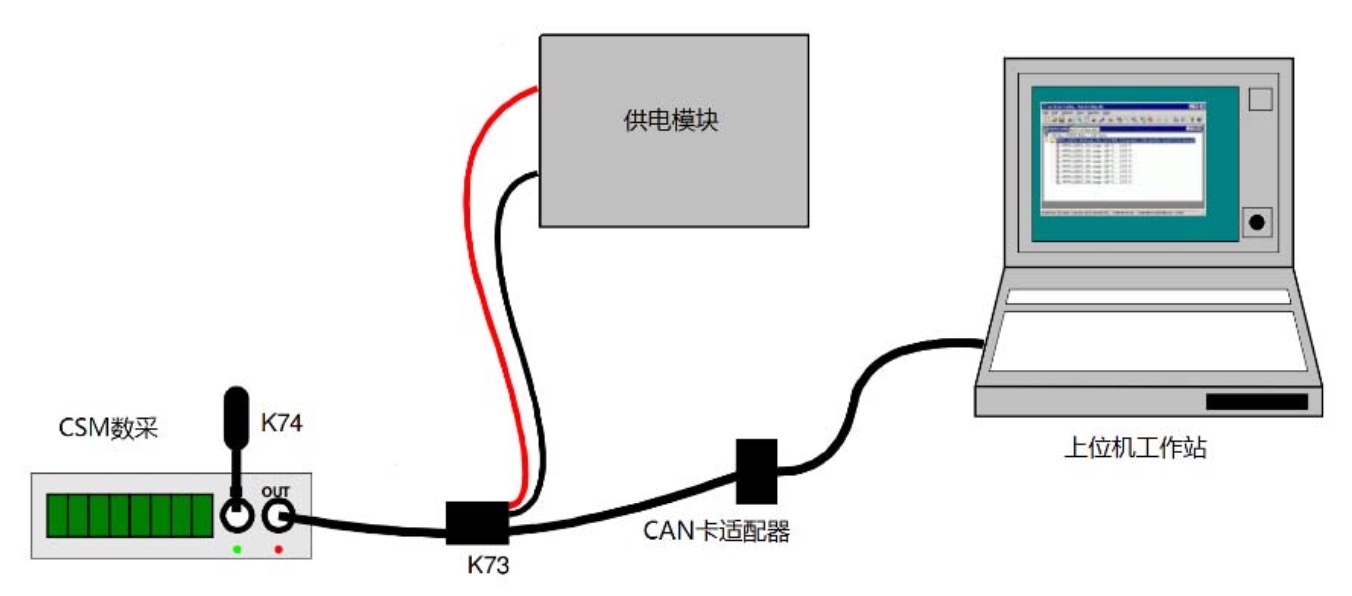 |
| Features | Widely used in the measurement of CAN fieldbus analog signals Up to 10kHz sample rate per channel State-of-the-art 4x32-point indexing table for nonlinear sensor characteristic curves (ADMM 4 pro HS) Available in 4 bipolar acquisition channel specifications, selectable input voltage, and protected with 500 volt electrical isolation Multiple ranges from 10mV to 60V are available, and each channel can be individually configured High-precision setting of sensor excitation, suitable for connecting various resistive sensors to work Wide operating temperature range: -40°C to 125°C The sturdy aluminum metal shell design has the highest international standard of moisture and dust resistance: IP67 Each acquisition channel is individually equipped with an LED display light to effectively monitor its working status |
| Brand and origin | CSM (Germany) |
| key parameter | Input information measurement range: ±10mV~±60V Sensor excitation: ±5V~±15V Resolution display range: 16Bit Sampling frequency (single channel): 10K Hz Overvoltage Protection: ±100V, ESD Protection Signal Filtering: 6th order Butterworth filter, 0.1-2K Hz cutoff frequency Non-linear scale: 32 points Working voltage: 5V-60V DC Weight: 300g Working temperature: ‐40~125℃ Moisture class: IP67 |
| Application | Sensor data collection |
Pedal force sensor
| Sensor appearance | 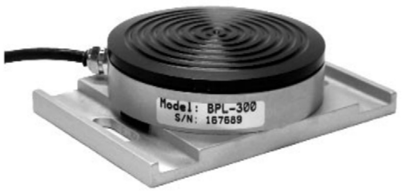 |
| Tooling and Dimensions | 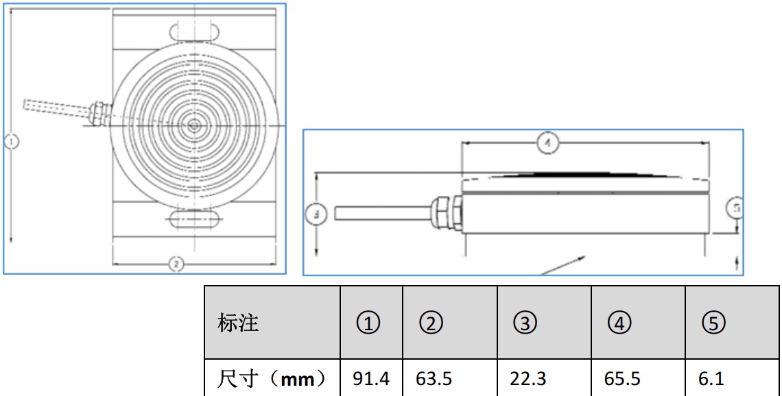 |
| Features | High-precision test indicators. Nonlinearity<0.05% Ultra light weight Ultra-thin geometry, compact and high-strength design multifunctional fixture Various sizes of pedal force tests are possible |
| Brand and origin | Interface (US) |
| key parameter | Measuring range: 200~2000N (the range can be customized) Weight: 250g Accuracy: ≤0.05% F.S Repeatability: ≤0.02% F.S Sensitivity: 2mV/V Zero offset: ±1%RO Maximum supply voltage: 15VDC Recommended supply voltage: 10VDC Working temperature: ‐55~90℃ Maximum overload: ≥150% Signal line: 3m |
| Application | Vehicle pedal force parameter test |
Angle sensor
| Sensor appearance | 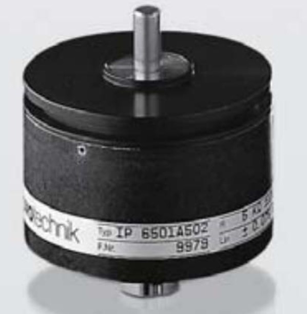 |
| Tooling and Dimensions | 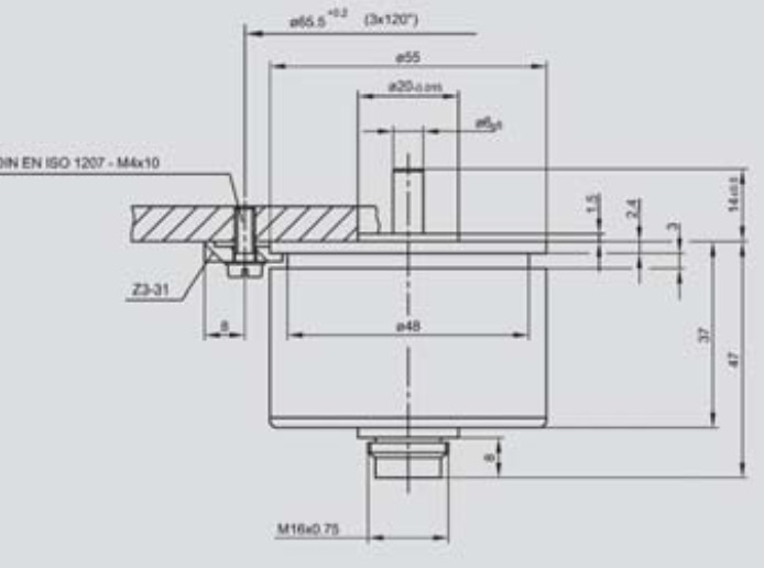 |
| Features | Industrial product standard size Long service life: >10 million times Excellent linearity: ±0.075% High resolution, better than 0.008° The maximum speed allowed is 10000 rpm Unlimited continuous spin |
| Brand and origin | Novotechnic (Germany) |
| key parameter | Mechanical stroke: 360° continuous Maximum speed: 10000 R/min Working range: 350 ±2° Repeatability: ≤0.002% Independent linearity: ±0.075% Maximum working voltage: 42V Seismic index: 5-2000Hz Working temperature: ‐40~100℃ |
| Application | Pedal stroke angle information measurement |
Motion detector
| Sensor appearance | 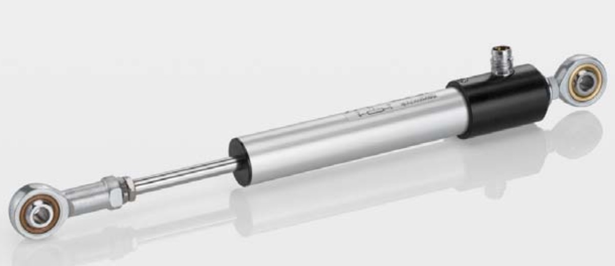 |
| Working range parameters | 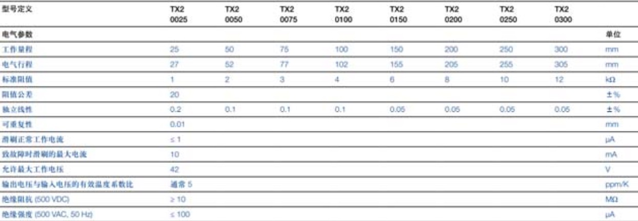 |
| Features | The output signal can be customized Long life: 2 million times High linear accuracy Connection: high strength cable (standard length 1M) Protection: IP65 |
| Brand and origin | Novotechnic (Germany) |
| Key parameter | Compact body: 16mm Output signal: voltage Electrical stroke: 25‐300mm Accuracy: 0.05% comprehensive) Life: 50 million times Working temperature: -40℃ - 85℃ Reciprocating speed: 5 m/s Protection class: IP 67 |
| Application | Pedal track travel information measurement |
Handbrake force sensor
| Sensor appearance | 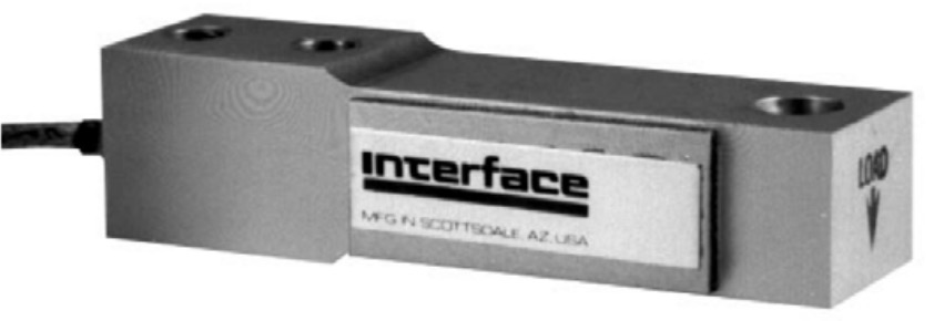 |
| Tooling and Dimensions | 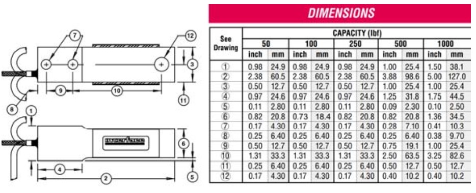 |
| Features | Ultra-thin structure design, as close as possible to the actual handbrake force measurement Convenient and practical. Simultaneous testing of handbrake angle First-class company products, strict engineering testing |
| Brand and origin | FGP (France) |
| Key parameter | Measuring range: 50~1000LBF Accuracy: ≤0.03% F.S Sensitivity: 1.5mV/V Zero offset: ±5%RO Recommended supply voltage: 10VDC Working temperature: ‐55~90℃ Maximum overload: ≥150% |
| Application | Parking handle force measurement |