Analysis of EMC testing standard ISO21498 for electric vehicles
With the pace of automotive electrification, EMC testing of electric vehicles is increasingly becoming an indispensable part of the vehicle development field. Zell Testing, in collaboration with AMETEK CTS and EN-IMPEDANZ, has established a world's most advanced and cutting-edge solution for conducting immunity and conducted emission testing of EMC high-voltage components.
The most representative high-voltage component testing standards currently include ISO21498. Below, we will analyze the corresponding standards and provide corresponding solutions.
1、 ISO21498 Electric Road Vehicles - Electrical Specifications and Tests for B-Class Voltage Systems and Components
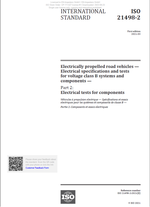
This standard is divided into two parts:
Part 1: Voltage subclasses and characteristics
Part 2: Electrical Testing of Components
ISO21498-1 mainly provides definitions of voltage subcategories and characteristics for rechargeable energy storage systems (RES) and electric propulsion systems. It defines the specified values of these subcategories based on the maximum operating voltage, where the listed voltage subcategories are used for voltage level B systems of various current or future electric road vehicles. ISO21498-2 provides electrical testing for Class B voltage electrical and electronic components used in electric road vehicles. Considering the typical driving scenario and deviations from normal operation, it covers all relevant characteristics and provides a general description of the purpose, settings, procedures, and requirements of the test.
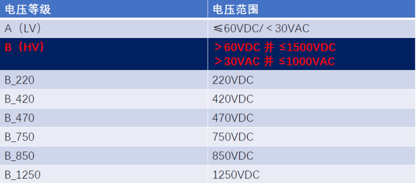
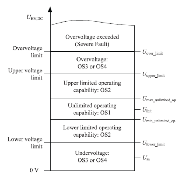
The voltage level and operating status specified in ISO21498-1:
Voltage level
running state

Testing standards and corresponding solutions in ISO21498-2

Zeer provides corresponding solutions for the testing items in ISO21498. Voltage change testing is measured using AC/DC power supply NetWave/PowerWave, while emission testing requires a comparable load environment in conjunction with the corresponding EN-IMPENDANZ artificial impedance network to complete voltage slope and voltage ripple generation testing. The most important thing is voltage ripple testing, which needs to be combined with a ripple generator to give the DUT a corresponding amplitude ripple to complete.
Installation setup diagram
Installation and setup diagram for voltage change testing
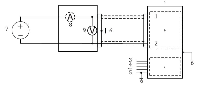
1. B-level voltage connection: HV+
2. B-level voltage connection: HV-
3. A-level voltage power
4. I/O and bus signals
5. Directly connect to the voltage level A grounded terminal
6. Electric chassis
7. High voltage DC power supply
8. Current sensor (optional)
9. Voltage sensor (reference value for UHV)
a. DUT
b. B-level voltage circuit
c. A-level voltage circuit
Installation and setup diagram for launch testing
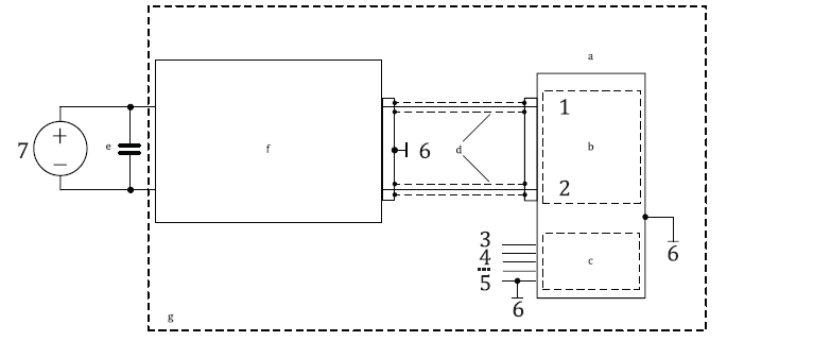
1. B-level voltage connection: HV+
2. B-level voltage connection: HV-
3. A-level voltage power
4. I/O and bus signals
5. Directly connect to the voltage level A grounded terminal
6. Electric chassis
7. High voltage DC power supply
a. DUT
b. B-level voltage circuit
c. A-level voltage circuit
d. The length of cables that are consistent with the interior of the vehicle should be agreed upon by the supplier and customer (not exceeding 2 meters)
e. Decoupling capacitor CS
f. Artificial Network AN
g. Grounding plane
For launch testing, the artificial network framework is shown in the following figure
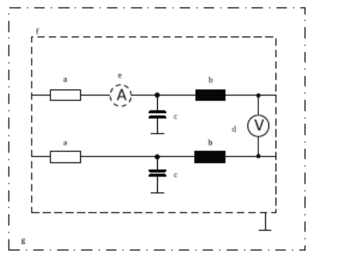
a. Ri, HV
b. LV
c. CY
d. Voltage sensor (reference value for UHV)
e. Current sensor
f. Shielding box (optional)
g. Grounding plane (optional)
The values of Ri, HV (internal resistance of vehicle power supply), LV (vehicle inductance, mainly vehicle power supply and cables), and Cy (capacitor between HV+/HV and ground, used to limit electromagnetic compatibility) are given in the table below. These values correspond to typical vehicle system values, where parasitic electrical induction in artificial networks is less than 500nH.

Among them, Z case is based on the actual situation of the customer, and Zell strongly recommends a resistance of 50m Ω, which meets the typical vehicle impedance value of most main manufacturers for 800V platform electric vehicles.
Installation and setup diagram of voltage ripple immunity
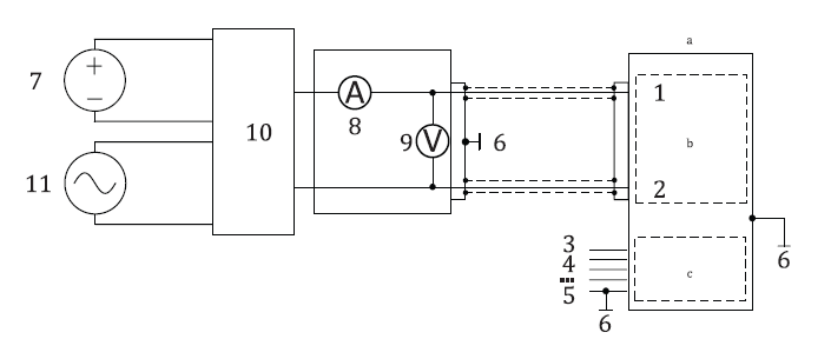
1. B-level voltage connection: HV+
2. B-level voltage connection: HV-
3. A-level voltage power
4. I/O and bus signals
5. Directly connect to the voltage level A grounded terminal
6. Electric chassis
7. High voltage DC power supply
8. Current sensor (optional)
9. Voltage sensor (reference value for UHV)
10. Coupling/Decoupling Network
11. AC voltage source
a. DUT
b. B-level voltage circuit
c. A-level voltage circuit
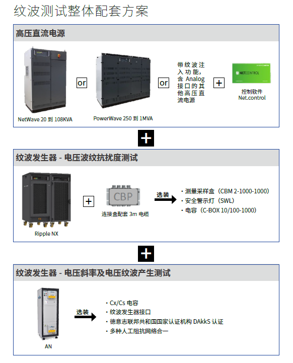
Specifically analyze the installation and setup diagrams for all tests. Firstly, conduct voltage change tests. Depending on the specific requirements of different tests, there may be differences in the position of the electric floor pan, but the overall framework remains unchanged. Secondly, for emission testing, both the voltage slope test generated in 6.3 and the voltage ripple test generated in 6.5 need to be combined with artificial networks for testing, while the voltage mutation test generated by load shedding in 6.10 does not need to be combined with artificial networks. Please refer to the standard for specific installation and testing diagrams. The installation diagram for voltage ripple testing needs to be combined with 11 AC voltage sources and 10. Coupling/decoupling networks to complete the testing. Our ripple generator RIPPLE NX is a highly integrated device that integrates ripple generation sources, decoupling capacitors, and coupling transformers, perfectly covering the installation requirements for ripple immunity testing required by the standard.
For more product information, please contact Chongqing Zeer Technology Co., Ltd
Phone number 18221809217 (same as WeChat)